maintained by
updated December 2004
New: A tour of Steve Hemphill’s Workshop!
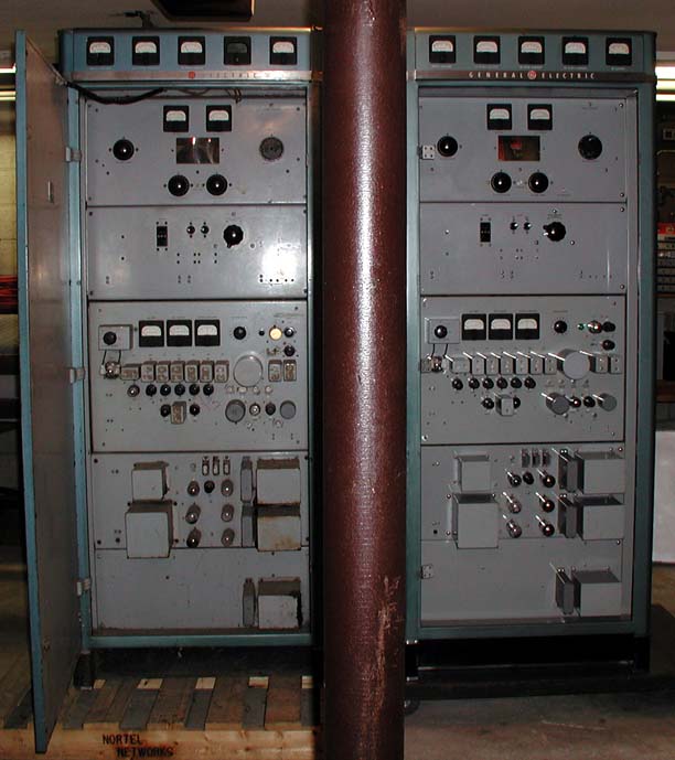
Steve sent me these pictures of his Phasitron transmitter restoration workshop back in the spring of 2003, and I have been derelict in my duty to get these posted. So with apologies to Steve, here are the photos that document his stunning work on restoration of not one, but two GE 250 watt Phasitron FM transmitters. This picture shows a "before" transmitter on the left, and an "after" transmitter on the right:
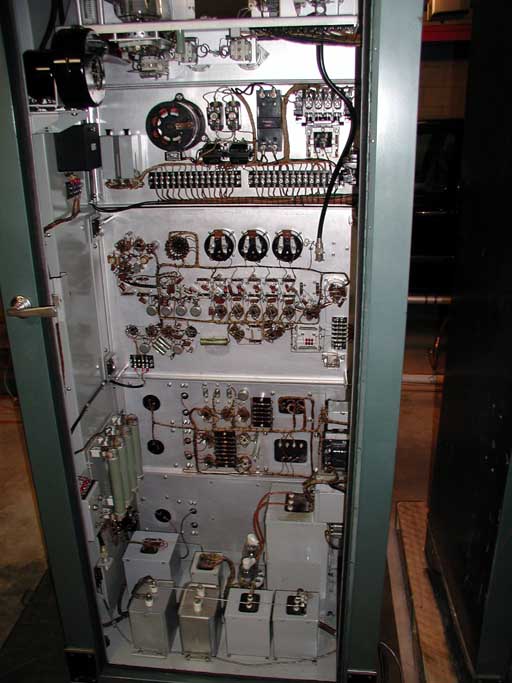
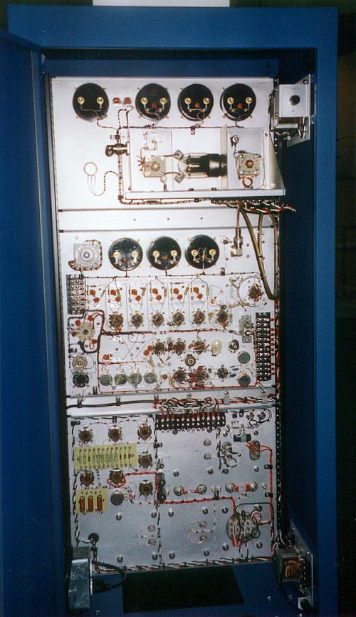
Here is the rear of the restored Phasitron transmitter. It looks brand new:
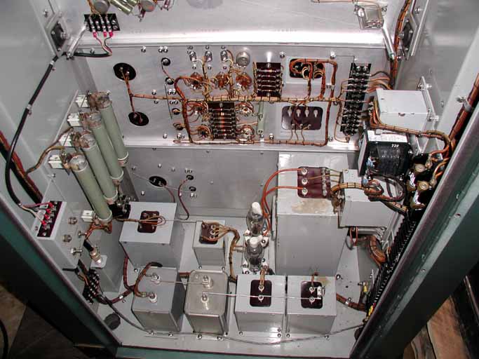
Here is a closeup view of the lower part of the transmitter – the power supply section, with all of the "heavy iron" components:
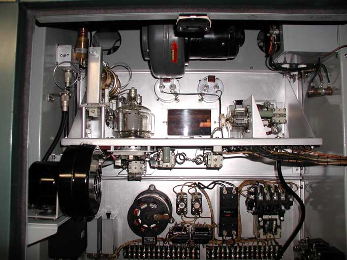
And finally, here’s a closeup of the 250 watt push-pull PA:
Steve Hemphill's Alpine Tower Project
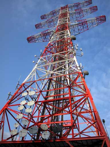
Steve is working on a "re-enactment" of Major Armstrong's 44 MHz FM broadcasts from Alpine tower in New Jersey. Here's the Alpine tower:
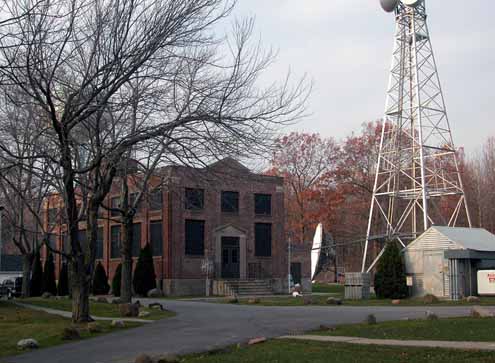
And here is Major Armstrong's original transmitter building built in 1937 that housed the W2XMN station (the world's first FM broadcast station) - now the Alpine museum:
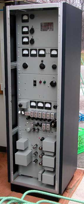
Steve has built a Phasitron FM transmitter operating at 44.1 MHz for this project. Although the Phasitron was not even invented yet when Armstrong began his broadcasts, the technology is approximately correct for the era. Here is Steve's 44.1 MHz transmitter, sitting just outside of the Alpine Tower equipment room:
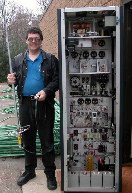
Gorgeous work, Steve! Here is a view of the back side of the transmitter, and the front side of Steve, who is holding a Ringo Ranger antenna modified for use at 44.1 MHz. Hopefully, the transmitter was not operating when this picture was taken:
Steve says that the commemorative broadcasts will be done sometime in the spring or early summer of 2005. (I hope he will QSL!)
PHASITRON NEWS FLASH: Steve Hemphill builds reproduction of Phasitron exciter, shown at NAB2002!
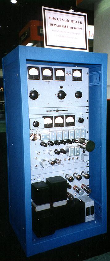
There was a special treat in store at NAB 2002, in the Belar booth. Steve Hemphill has built a working reproduction of a 1946 GE model BT-11-B 10 watt FM transmitter/Phasitron exciter! Here's a picture of it:
Steve's labor of love has produced a gorgeous Phasitron exciter, that looks like it just rolled off the GE assembly line over half a century ago! Steve built the exciter mainly using an original technical manual as the reference. Almost every detail is authentic - all the way down to the beautifully made shield covers for the frequency multiplier tuned circuits, and the mu-metal shield for the Phasitron tube itself. And, the exciter works! Arno Meyer told me, "It makes 1% distortion at 50 Hertz!" (In a phase modulator system, the greatest distortion comes at the lowest frequencies where the phase modulation is highest.)
And here's the rogues' gallery:
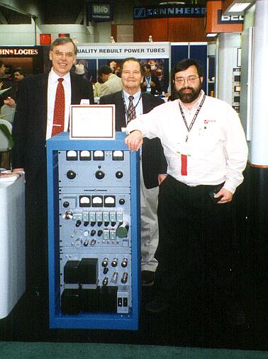
From left to right in this picture: Geoff Mendenhall, W8GNM (ex-W9NEZ), an engineering vice president at Harris Broadcast in Mason, Ohio; Arno Meyer, founder and president of Belar Electronics; and Dave Hershberger, W9GR (creator of this web page), principal engineer at Axcera.
Steve Hemphill used Arno Meyer's facilities at night to produce the Phasitron exciter reproduction.
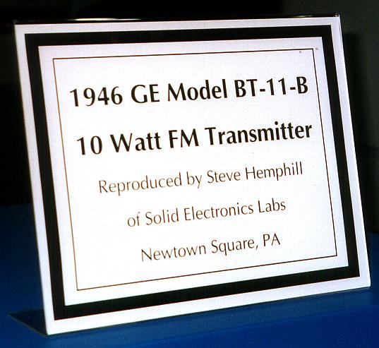
Here's the sign that appears on top of the exciter:
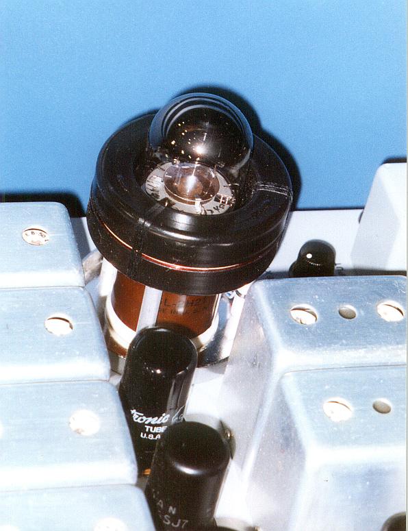
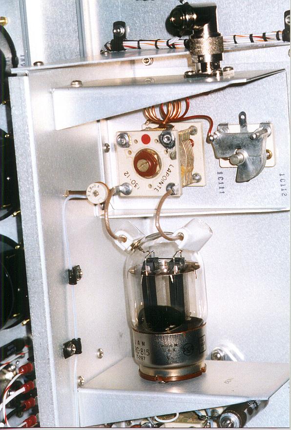
Here's the Phasitron tube (with the mu-metal cover removed) in its natural habitat - inside the modulator coil:
The back of Hemphill's exciter is beautiful:
Here's a closeup of the 10 watt PA in the exciter:
Steve was unfortunately unable to attend NAB this year but he was pleased to hear that his handiwork attracted lots of attention.
I talked to Steve after NAB and we discussed the idea of running stereo composite through the Phasitron, and possibly even putting it on the air. Steve said that he widened out the bandwidth of the first multiplier or two to 100 kHz either side of carrier, and that he was able to get about 25 dB of stereo separation that way! And, he even passed a RBDS subcarrier through the Phasitron! But alas, widening out the bandwidth produced unwanted harmonic multiplier sidebands on either side of the output signal, which exceeded FCC rules. Steve had to narrow the bandwidth of the multipliers back to the original 30 kHz to meet occupied bandwidth rules.
But I suggested that Steve might be able to equalize the stereo composite with a two-section baseband equalizer (rising at 12 dB/octave) to overcome the (doubly tuned) first multiplier's narrow bandwidth, and get decent stereo separation.
Now that would be a first - stereo from a Phasitron tube!
(UPDATE: see link to Steve's e-mails below - he did it! The Phasitron has gone stereo!)Bill Gillman suggested breaking the multiplier chain partway up, and inserting a second Phasitron tube to inject the L-R modulation.
Radio World conferred upon Steve an honorary "Cool Stuff" award for his Phasitron exciter. "Cool Stuff" awards are normally given to new products. But even though the Phasitron exciter is 56 years old, it was still too "cool" to pass up by the awards committee at Radio World.

Radio World's 2002 Cool Stuff Here's the link to Radio World's 2002 "Cool Stuff" awards.
E-mail from Steve Hemphill to Paul McLane and the Phasitron goes STEREO - Steve Hemphill himself provides background information and details on the construction of his Phasitron exciter - and he reports on the successful development of a composite baseband equalizer, allowing FM STEREO to come out of a Phasitron!
Question: which station had a Phasitron FM exciter on the air, in regular service, at the latest date?
I would like to know how long Phasitron rigs were on the air. Some people who have sent me e-mails talk about various FM stations that had Phasitrons on the air until about 1970, or the early 1970s at the latest. But I think my first college's FM station has that beat.
WGCS 91.1 FM in Goshen, Indiana had a Phasitron equipped GE 250 watt FM transmitter in regular service until the fall of 1979. In fact, it was their only transmitter. Of course, if you had a Phasitron rig, you were on the air in mono. To go on the air in stereo, WGCS replaced their old 250 watt GE with a 5 kilowatt Gates FM-5H with a TE-3 exciter. (They raised power at the same time, obviously.) If anybody knows of an FM station that had a Phasitron rig on the air in regular service later than 1979, please let me know. E-mail me here: Click to email me. To qualify, the Phasitron rig must have been the main transmitter in regular use, not a backup.Other Phasitron news - two versions of the tube:
Some e-mails I have received recently have informed me that there were two different kinds of Phasitron tubes made by GE. Two different tube historians have written to me about the 2H21 and 5593 incarnations of the Phasitron. One of the tube historians wrote to me:
As a tube-history enthusiast, I've tried hard to figure out any real difference between the 2H21 and 5593 from the GE data sheets. (The 2H21 is rated to 500 kHz; the 5593 is derated to 250 kHz.) Pinouts are the same but the internal structure may be just slightly different, judging from the photos. The 5593 could've easily been called "2H21A," but for marketing reasons, when the EIA gave up "1A21"-formatted tube identifiers in favor of "5500"-format, the old scheme looked dated.
To swamp you with trivia, "2H21" was a mistake. The RMA/EIA number assigner must've counted the electrodes, gotten eight "usable electrodes," and therefore used "H," which was the code for octodes. Trouble is, there was a much more elegant letter, "T," for "storage, radial-beam, and other special deflection-control tubes" which would've
been a lot more suave. "T" got assigned only once, then abandoned.
I believe that the GE 250 watt FM transmitter used at WGCS used the GL-5593 version of the Phasitron.
Here’s a link to an online tube manual page (with some VERY good closeup photographs of the tube itself) run by Jeremy M. Harmer:
http://www.tubecollector.org/5593.htmSo much for the news flash - now to the "standard" Phasitron web page information:
Greetings to all fellow aficionados of obsolete, but brilliant technology. And a special welcome to people who are, or who want to be fascinated by the Phasitron tube!
For those who are unfamiliar with the Phasitron, it was a very clever application of vacuum tube technology to solve a problem: creating a phase modulator that had a very wide (+/- 360 degrees or more) and very linear phase modulation characteristic. This allowed a lower frequency multiplication factor in FM broadcast transmitters that used phase modulation.
In the early days of FM, there were two ways of generating an FM broadcast signal.
One way was to frequency modulate a conventional L/C oscillator. The advantage of this method was that it was very easy to achieve wide frequency deviations. The disadvantage of this method was that an automatic frequency control system was required to keep the L/C oscillator on frequency. This was in the days before frequency dividers and phase locked loops. Frequency control was inaccurate (compared with crystal oscillators) and it was a kludge! One transmitter system made by RCA actually used a motor driven variable capacitor system to keep the transmitter on frequency! Such systems also had a certain amount of inherent time delay in the frequency correction system, which meant that frequency errors would persist for a while before they were corrected.
The other way to produce FM, which was more commonly used, was to produce phase modulation instead of frequency modulation. Phase modulators, unlike frequency modulators, could be used with unmodulated carriers provided by crystal oscillators. This eliminates the frequency control problem, but introduces another: getting a wide enough frequency deviation.
Phase modulation and frequency modulation are close cousins. Frequency modulation is the rate of phase modulation. In other words, the amount of frequency modulation is the time derivative of the phase modulation. In a phase modulation transmitter, as the modulating frequency is increased, the phase modulation stays the same but the frequency modulation increases. In a frequency modulation transmitter, as the modulating frequency is increased, the amount of frequency modulation stays the same, but the phase modulation decreases. This means that FM and PM are really the same thing except for a frequency response issue. So, by applying a 6 dB per octave descending slope to the audio frequency response, FM could be produced by a phase modulator.
The problem is that the amount of phase modulation (in radians) necessary for simple monophonic audio is the necessary frequency deviation divided by the modulating frequency. (This is also called "modulation index.") So if you want to have 75,000 Hz deviation at 15,000 Hz, you need 5 radians of phase modulation, or about 286 degrees. But if you want 75,000 Hz of deviation at 50 Hz, you need to provide 1500 radians of phase modulation, or 85,943 degrees! Since most phase modulators produce small amounts of phase modulation, the problem of obtaining huge amounts of phase modulation was solved by using frequency multipliers, which not only multiply the carrier frequency, but also any phase or frequency modulation.
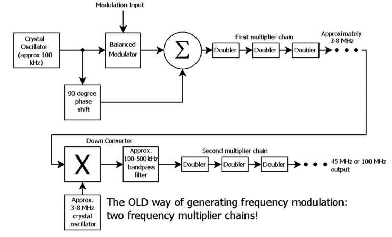
The original Armstrong type FM transmitters used a simple quadrature balanced modulator to obtain FM from phase modulation (PM). They started out around 100 kHz, frequency multiplied up to about 6-8 MHz, then heterodyned the signal back DOWN to 100 kHz, then multiplied back up again to either the 40 or the 88-108 MHz FM bands. The double multiplication chain was necessary because the balanced modulator only produced about 10-15 degrees of phase modulation before its distortion became large. It took a lot of frequency multiplication to turn such small amounts of PM into 75 kHz of FM, especially at low modulating frequencies. Here's a block diagram of the early Armstrong type FM transmitter. (The frequencies and multiplication factors may not be quite correct.)
The Phasitron tube solved that problem by providing huge amounts of phase modulation. The Phasitron was actually a form of CRT in the sense that it used focused electron beams. It produced a thin, focused disk of electrons, flowing radially to a pair of concentric cylindrical anodes. One anode had slots punched in it so that some of the electrons would hit the inner anode, and others would go through the slots and hit the second anode. Then, using a three phase excitation on three sets of radial grid wires, "ruffles" were formed on the electron disk. (Around the periphery of the electron disk, the edge was bent up and down.) The three phases were set up so that the "ruffles" would rotate. The slots in the inner anode were also staggered so that at one instant, most of the electrons would be going through the slots to the outer anode. 180 degrees later, the electrons would miss the slots and hit the inner anode. So, the output from the tube was taken differentially from the two anodes.
Now comes the interesting part. Apply a magnetic field axially to the tube, and the electron disk (and its "ruffles") will twist clockwise. Apply the field the other way, and the electron disk will twist counterclockwise. This produces phase modulation - a lot of it.
So, the Phasitron tube was mounted in a coil that had the station's pre-emphasized audio applied to it. With an audio voltage applied to the coil, the magnetic field was the integral of the applied voltage. So, the phase modulation was also the integral of the applied voltage. That meant that the "phase modulation" coming out of the tube was actually FREQUENCY modulation. The coil, in effect, was converting PM to FM by virtue of its 6 dB per octave slope!
So, the whole system was downright clever. A tube that produced FM, yet with crystal controlled accuracy!
There was an article published in the January 1947 issue of the Proceedings of the IRE (before I was born).
When I was in college, the campus FM station had an old General Electric 250 watt transmitter that used a Phasitron tube. I read the manuals and developed an appreciation for the clever thought and engineering that went into it.
At that time (1970), Phasitron tubes were no longer being made. There were rebuilt Phasitrons which were being sold for $600 apiece - a lot of money in those days. The college FM station had one Phasitron in the transmitter, and two spares on the shelf.
Sometime in the 1940s (no later than 1948 - that date supplied by John Byrns - thanks!), the "Serrasoid" wide-range phase modulator was developed by REL and later used by ITA, Gates, and probably others. That system used oscilloscope sweep-type ramp waveforms to generate large amounts of phase modulation, but that's another story.
Last summer, I got it in my head that I wanted to have a Phasitron tube to sit on my desk and inspire myself to think of weird (but hopefully useful) ways to generate radio signals. I put out the word to the Radio Technology mailing list on Broadcast.Net, and Bill Gillman (WB7RFS) responded. Bill is similarly fascinated with the Phasitron tube, and he has his own Phasitron "trophy" sitting on his shelf. Bill told me where he got his, and I was able to get mine from the same source (Salt Lake Instruments, in Salt Lake City; unfortunately, they're sold out now).
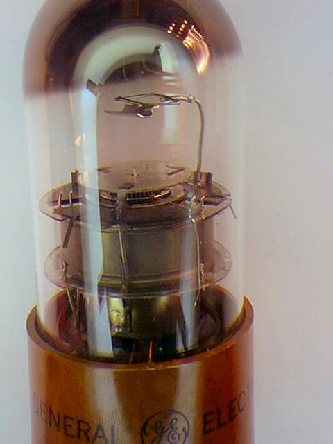
Here's what you came here for - a picture of my Phasitron tube:
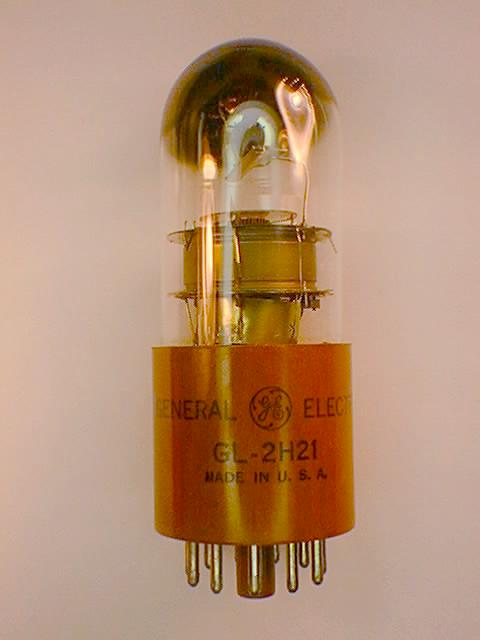
And here's a closeup of just the "guts" in the tube:
Now if I could just find an authentic Phasitron COIL to go around it!
Want to read the article from the January 1947 issue of the Proceedings of the IRE describing the Phasitron? Click here:
Original Adler article describing the Phasitron (HTML; approximately 1.3 megabytes including 20 images)
Original Adler article describing the Phasitron (PDF file; approximately 1.3 megabytes)
Thanks to Bill Gillman, here are the GE tube manual pages pertaining to the Phasitron:
GE tube manual pages for the GL-2H21 Phasitron (HTML file; approximately 321 kbytes)
Here's an excerpt from a 1948 book on FM that discusses the Phasitron tube:
Excerpt from "FM Transmission and Reception" by Rider (HTML; approximately 680 kbytes including 8 images)
Excerpt from "FM Transmission and Reception" by Rider (PDF file; approximately 966 kbytes)
Here are some comments I got from various people who have looked at this page:
E-mail from Jack Sellmeyer - Jack recalls the RCA "Iron Fireman" direct FM exciter.
E-mail from Ben Crutchfield - Ben recalls using a Phasitron, and includes a picture of his own Phasitron tube.
E-mail from Dave Hultsman - Dave Hultsman (of Continental Electronics) recalls the microphonic aspects of the Phasitron tube.
E-mails from John Byrns - John Byrns provides many relevant details, including the correct date for the introduction of the Serrasoid modulator (1948).
E-mails from Roy Trumbull - Roy has some funny radio stories to relate in addition to further information on the Serrasoid modulator and other early FM gear.
Stan Slonski came across this site, that has a photo of the exciter in a GE Phasitron transmitter:
http://broadcastpioneers.tripod.com/whhs1.html
Chris Nystrom produced this most excellent PDF reproduction of an excerpt from "F-M Simplified" by Milton S. Kiver, published by Van Nostrand in 1947: FM Simplified